Data Sheet
AD636
Rev. E | Page 11 of 16
slightly more restricted than in the dual supply connection. The
load resistor, RL, is necessary to provide current sinking capability.
C2
3.3礔
AD636
ABSOLUTE
VALUE
SQUARER
DIVIDER
10k&
10k&
CURRENT
MIRROR
C
AV
BUF
+
20k&
NONPOLARIZED
39k&
0.1礔
0.1礔
+V
S
V
OUT
R
L
k&TO 10k&
IN
1
2
3
4
5
6
7
14
13
12
11
10
9
8
V
IN
NC
V
S
C
AV
dB
BUF OUT
BUF IN
NC
NC
NC
COM
R
L
I
OUT
N =N NNE T
+
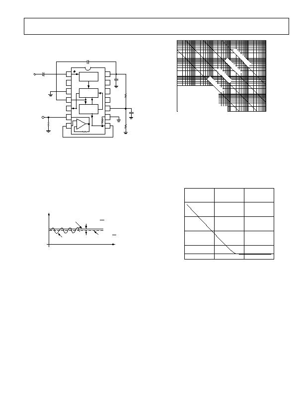
Figure 11. Single-Supply Connection (See Text)
CHOOSING THE AVERAGING TIME CONSTANT
The AD636 computes the rms of both ac and dc signals. If the
input is a slowly varying dc voltage, the output of the AD636
tracks the input exactly. At higher frequencies, the average
output of the AD636 approaches the rms value of the input
signal. The actual output of the AD636 differs from the ideal
output by a dc (or average) error and some amount of ripple, as
demonstrated in Figure 12.
TIME
IDEAL
E
O
DCERROR=E
O
E
O
(IDEAL)
AVERAGEE
O
=E
O
DOUBLE-FREQUENCY
RIPPLE
O
Figure 12. Typical Output Waveform for Sinusoidal Input
The dc error is dependent on the input signal frequency and the
value of C
AV
. Figure 13 can be used to determine the minimum
value of C
AV,
which yields a given % dc error above a given
frequency using the standard rms connection.
The ac component of the output signal is the ripple. There are
two ways to reduce the ripple. The first method involves using a
large value of CAV. Because the ripple is inversely proportional
to C
AV
, a tenfold increase in this capacitance effects a tenfold
reduction in ripple. When measuring waveforms with high crest
factors (such as low duty cycle pulse trains), the averaging time
constant should be at least ten times the signal period. For example,
a 100 Hz pulse rate requires a 100 ms time constant, which
corresponds to a 4 糉 capacitor (time constant = 25 ms per 糉).
INPUT FREQUENCY Hz
100
0.01
1
10
0.1
1
10
100
0.1
0.01
0
.
0
1
%
E
R
R
O
R
0
.
1
%
E
R
R
O
R
*% dc ERROR + % RIPPLE (PEAK)
1
%
E
R
R
O
R
1
10
100
1k
10k
100k
VALUES FOR C
AV
AND
1% SETTLING TIME FOR
STATED % OF READING
AVERAGING ERROR*
ACCURACY ?0% DUE TO
COMPONENT TOLERANCE
1
0
%
E
R
R
O
R
Figure 13. Error/Settling Time Graph for Use with the Standard RMS
Connection
The primary disadvantage in using a large CAV to remove ripple
is that the settling time for a step change in input level is
increased proportionately. Figure 13 shows the relationship
between C
AV
and 1% settling time is 115 ms for each microfarad
of C
AV
. The settling time is twice as great for decreasing signals
as for increasing signals (the values in Figure 13 are for decreasing
signals). Settling time also increases for low signal levels, as
shown in Figure 14.
rms INPUTLEVEL
10.0
7.5
0
10mV
100mV
1.0
5.0
2.5
1V
1mV
Figure 14. Settling Time vs. Input Level
A better method for reducing output ripple is the use of a post-
filter. Figure 15 shows a suggested circuit. If a single-pole filter
is used (C3 removed, R
X
shorted), and C2 is approximately
5 times the value of CAV, the ripple is reduced, as shown in
Figure 16, and the settling time is increased. For example, with
CAV = 1 礔 and C2 = 4.7 糉, the ripple for a 60 Hz input is
reduced from 10% of reading to approximately 0.3% of reading.
The settling time, however, is increased by approximately a
factor of 3. The values of C
AV
and C2 can therefore be reduced
to permit faster settling times while still providing substantial
ripple reduction.
发布紧急采购,3分钟左右您将得到回复。
相关PDF资料
AD650SD
IC V-F/F-V CONV 1MHZ 14-CDIP
AD652SQ
IC V-F CONV SYNCH MONO 5V 16CDIP
AD654JNZ/+
IC CONV VOLT-FREQ 500KHZ 8DIP
AD7740YRM
IC CONVERTER V TO FREQ 8-MSOP
ADM1070ARTZ-REEL7
IC CTRLR HOTSWAP -48V SOT23-6
ADM1073ARU-REEL
IC CTRLR HOTSWAP -48V 14TSSOP
ADM4210-2AUJZ-RL7
IC CTLR HOTSWAP LV TSOT23-6
ADVFC32SH
IC CONV V/F F/V MONO TO100-10
相关代理商/技术参数
AD636JD/+
制造商:未知厂家 制造商全称:未知厂家 功能描述:RMS-to-DC Converter
AD636JDZ
功能描述:IC TRUE RMS/DC CONV MONO 14-CDIP RoHS:是 类别:集成电路 (IC) >> PMIC - RMS 至 DC 转换器 系列:- 标准包装:46 系列:- 电流 - 电源:1.2mA 电源电压:±18 V,36 V 安装类型:表面贴装 封装/外壳:16-SOIC(0.295",7.50mm 宽) 供应商设备封装:16-SOIC W 包装:管件
AD636JDZ
制造商:Analog Devices 功能描述:IC, RMS-DC CONVERTER, 1%, 1.5MHZ, DIP-14
AD636JH
功能描述:其他电源管理 RMS/DC CONVERTER IC RoHS:否 制造商:Texas Instruments 输出电压范围: 输出电流:4 mA 输入电压范围:3 V to 3.6 V 输入电流: 功率耗散: 工作温度范围:- 40 C to + 110 C 安装风格:SMD/SMT 封装 / 箱体:VQFN-48 封装:Reel
AD636JHZ
功能描述:IC CONV RMS-DC LOW LVL TO100-10 RoHS:是 类别:集成电路 (IC) >> PMIC - RMS 至 DC 转换器 系列:- 标准包装:46 系列:- 电流 - 电源:1.2mA 电源电压:±18 V,36 V 安装类型:表面贴装 封装/外壳:16-SOIC(0.295",7.50mm 宽) 供应商设备封装:16-SOIC W 包装:管件
AD636JHZ
制造商:Analog Devices 功能描述:IC, RMS-DC CONV, 1%, 1.5MHZ, TO-100-10
AD636JN
制造商:未知厂家 制造商全称:未知厂家 功能描述:RMS-to-DC Converter
AD636JQ
制造商:未知厂家 制造商全称:未知厂家 功能描述:RMS-to-DC Converter